Preventing Direct Lightning Strikes
The Beginnings
Protection against direct lightning strikes has been a subject of controversy since the days of Dr. Benjamin Franklin. In 1755, Dr. Franklin introduced a lightning strike collection system. Subsequently, it became known as the “Franklin System”, and the more contemporary name is the “lightning conductor”, air terminal or lightning rod.
Shortly after its introduction, a controversy developed between those who believed in sharp pointed rods and blunt rods. Since both of these views lacked a physical foundation or statistical data at that time, the debate continued until very recently.
The effectiveness of the Franklin System of stroke collection has been questioned for over 100 years. Again, because there was no foundational physics, no test data or organized statistics presented to justify the manufacturer claims, they continued in use because of the lack of alternatives or other acceptable standards.
In 1963, Dr. R. H. Golde(1) concluded a study of strike collection system data and reaffirmed the conclusion of Oliver Lodge and Richard Anderson from their work that “acceptance of a fixed value for the area protected by a lightning conductor is unjustified.” Then, expressing in a more positive manner: “The attractive range of a lightning conductor should be regarded as a statistical quantity depending primarily on the severity of the lightning strike.” They further added that “a lightning strike of average intensity would be attracted over a distance of about twice the height of the conductor.” Then a subsequent “however” described several mitigating factors that would compromise those estimates. All of these statements were made without any reference to any form of foundational physics. Random unorganized statistics formed the basis for all conclusions and recommendations resulting in a “we always did it that way” attitude.
Recent Events
From the completion of Dr. Franklin’s work, up to early 1960, no significant concept changes or improvements were made. However, some changes were made in the appearance, application or deployment methods for the lightning collector/conductor. No changes were made in the collector concept, beyond the addition of up to four points being oriented in several directions, usually 90° from the vertical. These changes were a potential improvement from the logic point of view but were not justified by statistics or physics.
The next step was to change the logic behind what was assumed to be the protected volume. The industry standards groups agreed that the “cone of protection” theory was optimistic at best and various groups seem to agree independently that the logic should switch to the “rolling sphere” concept. This theory was based on the premise that by reducing the assumed volume of protection from a cone to one where the height of the collector was used as the radius of a ball rolled against the collector, thereby reducing the assumed protected volume to that illustrated by Figure 1. Seldom was any attention given to facility height or the competitive factors.

Figure 1: Air Terminal Concepts Showing Cone of Protection (left) and Rolling Sphere (right)
As time marched on, the industry and related standards groups realized that the “rolling sphere” theory was also of limited success. There were no statistics or valid tests that substantiated the basic premise or confirmed the theory. This started a shift to the more sophisticated air terminals most to be known as “early streamer emitters” (ESEs). These devices were developed based on the premise that some form of sophisticated collector could be developed that would launch a collective streamer much earlier or extend it further than the conventional Franklin rod. Various techniques were implemented. Most have proven to be no better than the Franklin rod. Of the four or five concepts offered, only one appears to offer some slight improvement in launching the steamer, but the resulting benefit was not significant enough to justify the expense. As with all the ESEs, the few tests that were made proved to be inadequate in that the competition was not considered. Attempts to authorize a standard based on the ESEs have failed within the USA because at least two independent studies funded by the U.S. National Fire Protection Association (NFPA) failed to find any evidence of their value over conventional rods.(2 & 3)
Tests conducted by Professor Charles Moore and associates of the New Mexico Institute of Mining and Technology in the mountain top lightning laboratory in Socorro, New Mexico, proved that blunt rods are more effective than sharp rods or ESEs(4).
The most recent action was a significant study funded by the National Fire Protection Association (NFPA)(3). (NFPA publishes the NFPA-780 Standard for Lightning Protection in the USA.) The study was conducted by three independent Consultants(3) with impeccable credentials. Originally, the study was conducted to determine the validity of the ESE concept. To do so, the Consultants, out of necessity, also compared the ESE to the Franklin rod, which proliferated into an in-depth study of both system concepts. The study results were literally “earth-shaking” for the lightning protection industry. The study states the following conclusions:
- ESEs and Franklin Rods are of approximately equal capability or inadequacy.
- The only factor that supports the use of Franklin Rods is “historical precedent” and only the political pressure supports the use of ESEs.
- Neither ESEs nor Franklin Rods have any scientific foundation in that there is no relevance to the physics of collection, no valid test data and no verifiable statistics.
- The existing NFPA Standard 780 should be discarded or relegated to a “recommended practice” at best.
- The recommendation that the existing 780 standard does not satisfy the NFPA criteria for a standard.
- Formation of a new protection systems standards committee was recommended.
In September 1999, a technical paper was presented by an IEEE Life Fellow, Donald Zipse, to the PCIC Conference as a keynote technical paper on lightning strike protection(5). Most of the conference members were from the oil and petrochemical industry. The paper presents the charge transfer system (CTS), the generic name of the LEC Dissipation Array® System (DAS®) as the protection system of the future. The paper received many accolades from the attendees.
As a result of these events, more significant actions were initiated.
- IEEE has established a committee to prepare a standard based on the CTS (P1576). A third draft was completed in late October 2001. The final revision has been delayed to permit completion of a study being conducted by a group of Russian scientists considered experts in atmospheric physics and lightning protection.
- The NFPA refused to issue the proposed NFPA-781 ESE standard in 2000.
- The NFPA agreed to release the 2000 version of the NFPA 780 standard after significant political pressure and, because without the existing 780 standard, industry and government agencies would “have no standard”. This is a premise based on “something is better than nothing” philosophy.
It should be noted that the NFPA is not expected to issue a new lightning protection standard until the physics of protection is clearly defined and agreed upon by an appropriate group. The IEEE is the most likely and the obvious source of those data.
In summary, the present situation is as follows:
- The Franklin System of lightning collectors remains in use for political reasons.
- ESEs are not accepted in the U.S. because of a lack of technical foundation and field test failures.
- Blunt lightning collectors have been proven to be better than sharp-pointed rods and an ESE concept in a valid comparative test.
- The charge transfer system (CTS) or Dissipation Array® System has achieved worldwide acceptance within the most major industries and has completed over 34 years of history.
- Drs. Bazelyan, Raizer and Aleksandrov of the Russian Academy of Science, completed over two years of study centered on the charge transfer system (CTS) technology resulting in proof of the scientific foundation for the CTS concept as recorded in ten technical papers presented to several scientific societies(6).
The Scientific Alternative Strike Prevention with the Dissipation Array® System (DAS®)
DAS Composition and Functional Characteristics
The Dissipation Array® System (DAS®), generically known as a charge transfer system (CTS), is the only true lightning strike prevention system. That is, the system actually prevents the termination of lightning strikes within any area defined as “protected”. This includes the premise that there will be no terminations on any DAS protected component, including the Ionizer. A violation of this premise is considered a failure.
A typical functional DAS is illustrated by Figure 2 when under the influence of a storm cell. Referring to that figure, the three basic subsystems are illustrated. These are:
- The ground charge collector (GCC) is deployed such that it will collect the charge induced on the area or facility to be protected. This is analogous to the conventional grounding system except the GCC is a collector and not an earthing system for strikes. As such, the deployment objectives are totally different. In designing the GCC deployment, the engineer must ask the questions: “what am I protecting,” therefore “what must I discharge?” That information defines what must be included in the GCC circuit. As a special example, if a building is to be protected, building steel provides the best GCC function for that building.
- The charge conductor (CC) is analogous to the conventional down conductor; but should be thought of as an “up conductor” because its function is to conduct the collected charge to the ionizer, providing a low surge impedance path in the process. Building steel and towers are ideal charge transfer conductors.
- The charge transfer mechanism (the ionizer) is the charge transfer component, and the most design sensitive. Its function is to transfer the collected charge to the adjacent air molecules via a principle known as “point discharge.” The resulting ions make up what is known as “space charge”, a mixture of charged and uncharged particles. This space charge forms a shield between the protected site and the storm cell. The result of this shielding effect is a reduction of the electrostatic field within the sphere of influence of that space charge. The Ionizer may be designed to create the required space charge density independent of that to be protected.
Preventing Any Protected Site Facility from Generating an Upward Moving Leader
Preventing any protected site facility from generating an upward moving leader that could develop a conductive channel and initiate a strike to the site. These leaders are usually initiated by tall structures in excess of 200 meters in height or mountain top facilities of any height, where the combined elevation will permit a voltage on the uppermost structure in excess of 106 volts during the discharge process.Studies conducted by Dr. Bazelyan(6) and his associates developed the proof required to assess and eliminate this risk. It was found that the use of an optimized Ionizer that could build up and maintain a space charge in that potential strike zone that would prevent the launch of a collective leader through that space charge.
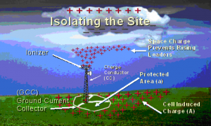
Figure 2: Typical DAS Installation Showing Three Subsystems
Since the objective of DAS® designers is to prevent lightning strikes to a given facility, the system design must accomplish two sub-objectives. These are (1) preventing any protected site facility from generating an upward moving leader, and (2) preventing terminations of descending lightning leaders.
A rare condition was experienced in areas where positive discharges were common and the launch of a rising lightning leader is common. In these cases the space charge density must be much higher than for the descending negative discharge. Peak lightning currents and related charges for positive discharges are initiated from earth to reach peak currents of up to 200,000 amperes. The negative discharges descending from the storm cell rise to peaks of only 80,000 amperes. It therefore requires nearly twice as much space charge in areas where the positive discharge is experienced; the electrostatic fields as usually much higher in those situations, thereby producing more ionization.
In any of these events, LEC found that the 100% effective ionizers designed are usually driven by the approaching lightning leader or very high electrostatic fields related to mountainous areas.
Preventing Terminations of Descending Lightning Leaders
Preventing the termination of a randomly delivered lightning leader is a significantly greater problem. The lightning leader is approaching termination at an average rate of up to 0.4 meters per microsecond for the last 100 meters or so. To deal with that closure rate, a significant volume of space charge must already be in place before leader propagation and the remainder will have to be generated as a reactive charge within 50 to 100 microseconds as the leader approaches.
LEC studies and field tests have proven that the properly designed DAS® ionizer can react and prevent stroke termination by generating a combination of the pre-strike space charge and a high density reactive charge when activated by the close proximity of the lightning leader.
The pre-strike space charge is fixed by the ionizer size, electrostatic field and the time between discharges and space charge migration rate. A combination of the electrostatic field, updrafts created by the storm and forces defined by Coulombs Law cause a constant flow of ion current and a constant migration of charge between the Ionizer and the storm cell as described by atmospheric physicist, Dr. Alton Chalmers(7). This space charge will impede the formation of the collective counter leader, if the charge density is high.
To understand the details of the termination phase of a lightning leader approaching a DAS, it is necessary to understand the leader situation just before “touchdown”. This is illustrated by Figure 3, a very unusual photograph that is paramount to understanding the DAS performance. It depicts the situation at a few microseconds before termination. Please note that there are many branches, with at least six in the foreground. All are about the same distance above earth; one must terminate. The objective is to prevent that one from termination on or in the DAS protected area.
The Typical Lightning Discharge
At least 6 possible terminations, which one "wins"?
Figure 4 superimposes this situation onto a DAS® protected tower site wherein one branch is approaching the DAS. The DAS responds by increasing the space charge density. Figure 5 illustrates the reactive space charge created by the approaching lightning leader branch. The resulting dense space charge suppresses the launch of a counter leader and the situation progresses to that illustrated by first Figure 6 and then Figure 7. One branch has now terminated on a tree, all of the other streamers are withdrawn; and finally, the DAS created space charge is also withdrawn through the DAS Ionizer creating a reverse discharge current flow, lasting only a few microseconds. All of those charges that are in the branches and around the ionizer take part in the neutralization function as illustrated by Figure 7. The earth returns to the normal negative state when the storm cells are discharged or not present.
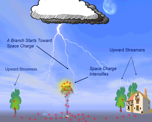
Figure 4: Lightning Branch Approaching Tower with DAS

Figure 5: Reactive Space Charge Created by the Approaching Lightning Leader Branch
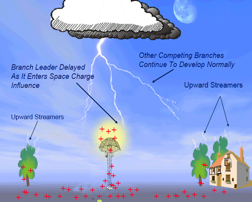
Figure 5: Reactive Space Charge Created by the Approaching Lightning Leader Branch
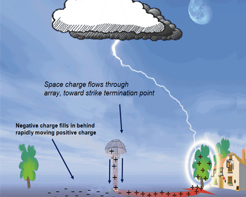
Figure 7: Charge Flowing to Strike Terminus, Others Returning to Neutral State
Note that the polarity on the ionizer has reversed. It changed from positive to negative because the former positive charge has been drawn away in the return stroke. As a result, the positive space charge has been retracted by the ionizer’s negative charge and transferred back into the return stroke channel through the earth between them.
The retraction process requires between one and three microseconds. That space charge has been estimated to contain no more than 100 millicoulombs (0.1 ampere-seconds). Therefore, the resulting di/dt could be between 30 and 100 kA/μs. However, this reverse current flow contains no destructive energy because of the very small charge that is being transferred in a very short duration.
Protection Area Considerations
Because of the DAS® operational concept, there are three factors that influence the size and shape of a protected area. These are:
- The number of branches from an incoming leader.
- The distance between the individual branches.
- The proximity between the DAS and the closest descending branch.

Figure 8: Current Flow Through DAS® During Thunderstorm
The number of branches from the leader will determine the random probability of one approaching the DAS site. A typical leader will start out and develop a few branches; however, by the time it reaches a few hundred meters from earth, it will have many branches as Figure 3 illustrates, up to 20 or more. Therefore, the chance of terminating to any point is less than one in twenty.
The distance between branches seems to vary from tens of meters to well over a kilometer at near ground level.
The foregoing two factors will influence the risk of termination on the site since they are subject to random probability. However, they both establish alternate paths for a termination if the DAS delays the progress of a branch approaching it. Therefore, these factors do influence the protected area. By delaying the termination of one branch the alternate termination point could be as close as 100 meters from the DAS or as far away as several kilometers. Again, this is a random variable; therefore, there is no way to predict the next closest termination point.
The proximity factor is the measure of the potential distance between the DAS and the closest potential termination point that would not be influenced by the DAS. This would also define the radius of the “protected area”.
DAS Application Criteria
The selection of a DAS ionizer is a semi-arbitrary decision. That is, there is no hard and fast rule, but rather, it involves a review of the influencing factors and a selection based on a tradeoff between those parameters. The factors that influence this decision are:
- The geographical location of the site and its related isokeraunic number.
- The height of the facility structures, and their related increased risk of high peak currents.
- The distribution of peak return current risk.
- The geography of the site.
The isokeraunic number (K) is related to the geographical location and the number of potential strikes (N) for a given square kilometer per year, where:
N = 0.04K1.25
So, if the isokeraunic number is 100, the average number of direct lightning strikes to each square kilometer in that area is expected to equal 12.7 strikes per year. (This equation is taken from IEC 1024-1-1.)
The height of the structure will determine the strike collection risk. Heights (H) of up to about 80 meters on flat land will collect the strikes within a radius of about 2H. Therefore, if the facility has an area of 0.1 square kilometers, and the expected number of strikes per square kilometer is 20, then the facility will collect about 2 strikes per year. However, structures of over 100 meters will initiate more strikes than the simple collection rate estimate. Further, the higher the structure, the larger the number of strikes initiated.
The distribution of peak currents in a return stroke is presented in Figure 9 which is based on worldwide data. So as an example, if a given location received 100 strikes per year, 50 would peak at 30 kA or less and one may peak at 100 kA. Unfortunately, this is a worldwide average. For mountain tops, the curve will skew to the right and peak currents in the range of 120 to 200 kA will make up 25 to 35 percent of the strikes. These will be a positive polarity and, therefore, require more ionization to delay the counter leader launch.
The geography of the site and its location will influence the risk of a strike termination. Only general rules can be used to deal with this parameter. These include:
- Mountain tops require maximum ionization to prevent strikes.
- Flat land and valleys require much less ionization to prevent strikes.
- Waterfront areas are very vulnerable to storms approaching from the sea; however, the peak currents are not as high as mountainous areas. The number of strikes is higher than that expected for that area based on the isokeraunic number.
General DAS Selection Rules
Again, most of the foregoing criteria are to be used as “guidelines”. However, there are some rules that must be considered mandatory. Where 100% strike prevention is required:
- The DAS® ionizer must be correctly sized to protect the desired area and/or structure.
- That ionizer must present a smooth surface without any discontinuities.
- Any ionizer of lesser size is based on accepting some level of risk acceptable to the customer.
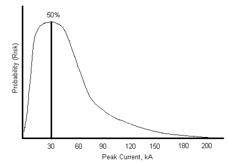
Figure 9: Distribution of Peak Lightning Currents
Conclusion
The data presented within the foregoing report present the results of over 34 years of research, development and the application of the Dissipation Array® System technology. The demand for proof of performance is reasonable; however, the definition of “proof” is more difficult. The Bryan Report (3) defined proof as including three constituents:
- Basic physics – the relationship between the protection and the related environment.
- Test data – instrumented assessment of performance.
- Statistics – the accumulation of significant sample size of operational systems.
Basic Physics
The basic physics have been established by Dr. Bazelyan et al.(6) and represents a departure from those early explanations used by LEC in prior publications. The key words are: The DAS delays the progress of an approaching leader/branch to permit termination elsewhere.
Test Programs
The test programs were and are the most difficult to execute. Lab tests are useful for optimizing DAS® design parameters. In-situ tests are the only acceptable form of test for a DAS. Two such tests were conducted in Singapore for government agencies. Three such tests were conducted in Japan on operational sites by Hitachi.
Statistics
The statistics on the operation of the DAS shows that 34-year history on over 2,400 systems and 30,000 system-years of operation has vindicated the DAS as scientifically sound. The DAS is now referred to generically as the “charge transfer system” or “CTS”.
In summary, the technology is sound, the basic physics has been established, the performance statistics are voluminous and the test data collected by LEC and others provides a firm foundation. The theory of operation has been expanded to provide a more detailed explanation of the final phases of the DAS protective actions, as the lightning leader completes termination elsewhere. The DAS design concepts remain virtually unchanged; some parameters have been refined and clarified over time.
References
1. Golde, Dr. R. H., Lightning, Academic Press, London 1977.2. Van Brunt, Dr. Richard J., et al., “Early Streamer Emission Air Terminals,” Lightning Protection System, January 1995.
3. Bryan, Dr. John S., et al, “Report of Third-Party Independent Evaluation Panel on the Early Streamer Emission Lightning Protection Technology,” September 1999.
4. Moore, Charles B., “Results of the Lightning Strike Contest,” Langmuir Lab, June 2001, (unpublished).
5. Zipse, Donald W., “Lightning Protection Methods, an Update and a Discredited System Vindicated”, IEEE Tran. Ind. App. Vol. 37, March/April 2001.
6a. “Necessity of Employment of Active Influence on Lightning in Contemporary Lightning Protection”, 25th International Conference on Lightning Protection, September 2002, Krakow, Poland.
6b. “Outlook on the Improvement of the Reliability of Lightning Protection by Injecting Space Charges,” 25th International Conference on Lightning Protection, September 2002, Krakow, Poland.
6c. “Initiation of Leader in Long Gaps at Quasi-Steady Corona Near Stressed Electrode,” 9th International Symposium on Gaseous Dielectrics, May 2001, Maryland, USA.
6d. “Numerical Modeling of the Gas Discharge Process in the Lightning Protection System,” 4th International Symposium on Electromagnetic Compatibility and Electromagnetic Ecology (EMC-2001), June 2001, St. Petersburg, Russia.
6e. “Initiation of Leader from Electrode with Corona in Long Air Gap,” All-Russian Scientific Conference on Physics of the Low Temperature Plasma, July 2001, Petrozavodsk, Russia.
6f. “Corona Discharge at the tip of High Grounded Electrode in the Electric Field of Thundercloud,” 12th International Symposium on High Voltage Engineering, August, 2001, Bangalore, India.
6g. “Effect of the Injected Space Charge on Lightning,” Fall Meeting of the American Geophysical Union (AGU), December 2001, San Francisco, California, USA.
6h. “The Effect of Coronae on Leader Initiation and Development under Thunderstorm Conditions and in Long Air Gaps,” Journal of Physics D: Applied Physics, 34 (2001), IOP Publishing Ltd., UK.
7. Chalmers, Dr. A., Atmospheric Electricity, Pergamon Press, London, U.K., 1967.
